
Go to documentation repository
To set the field variables, follow these steps:
- In order to set the field variables, it is necessary to select the variables of the object in the workspace, and open the Variables field in one the following ways:
- Click
 on the toolbar;
 In the object functional menu, select Properties.
Note.
The object functional menu is opened by right-clicking anywhere inside the object.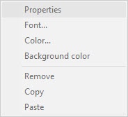
- Click
- The Field variables window will appear.
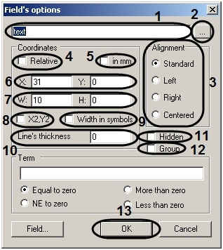
- In the text field (1) enter information describing the field:
- Enter text in Text field, which will be displayed in the text field.
- For Variable, enter the variable name.
- For an Image, enter the image address in quotes. The image must be placed in one of the following folders:
- In the Axxon PSIM software installation folder (e.g. C:\Program Files\Axxon PSIM), then in the field (1) enter the image name, e.g. “image.bmp”.
- In the Bmp folder of the Axxon PSIM software installation folder (e.g. C:\Program Files\Axxon PSIM\Bmp), then enter the image file address as "Bmp\image.bmp" or "Bmp/image.bmp".
- If you would like to fill in the text field with data from a text file or enter a large amount of data, then click the
 button (2) and use a text editor (see the section in APPENDIX 2. Entering text using the editor).
 - Set the Alignment settings for the desired justification of the text within a selected object (3).
- Select units of measure which will be used to size the object:
- If the size of the object will be given in millimeters, then check the in mm box (5).
If the size of the object will be given in characters [symbols], then check the Width in symbols box (9).
Note.
The size of the object is given in characters [symbols] by default.
- Set the position of the upper left of the object in one of the following ways:
- Specify the absolute coordinates of the object. In this case you should indicate the position of the upper left corner by setting the X-axis in the X field, and the Y-axis in the Y field: (6)
- Specify the relative coordinates of the object. In this case you should check the Relative box (4).
- The width and height of the object can be set in one of the following ways:
- Specify the width of the object in the W field, and the height of object in the H field (7).
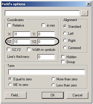
- Specify the coordinates of the lower-right corner. To do this, check the X2, Y2 box (8). The W and H fields will be by X2 and Y2. After this, specify the coordinates of the lower-right corner of the object using the X2 field for the x-axis and the Y2 field for the y-axis.
- Specify the line thickness in the Line thickness field in the desired units (10).
- If a custom object should be on the badge or there is a dialog window, but it should not be visible to the user, then check the Hidden box (11).
- If the object must be part of a group, check the Group box (12).
- Click OK (13).
Setting the variables is completed.
Overview
Content Tools