
Go to documentation repository
Previous page
![]()
![]() Next page
Next page
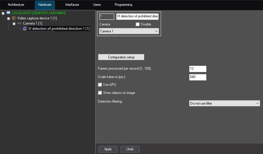
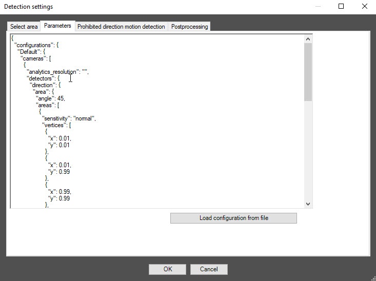
Configuring the VI detection of prohibited direction software module includes general settings and configuration settings: detection zone, configuration parameters and detection tool characteristics.
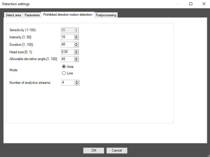
In the Intensity [1, 50] field, specify in arbitrary units in the range 1–50 how noticeable the object's movement in the detection zone must be for the detection tool to trigger. The default value is 10. If you enter a value out of range, it is automatically changed to the appropriate boder value. If you select the Line mode in the Mode parameter, this setting is disabled.
In the Duration [1, 100] field, specify in arbitrary units in the range 1–100 the duration of the object’s movement in the prohibited direction. It can be used when analyzing dense passenger flows, when an object making its way in the opposite direction appears in the camera’s FOV only for short time intervals, and the rest of the time is hidden from view by the crowd. The default value is 40. If you enter a value out of range, it is automatically changed to the appropriate boder value. If you select the Line mode in the Mode parameter, this setting is disabled.
Note
When you change the mode, all settings return to default values on the Select area tab.
Note
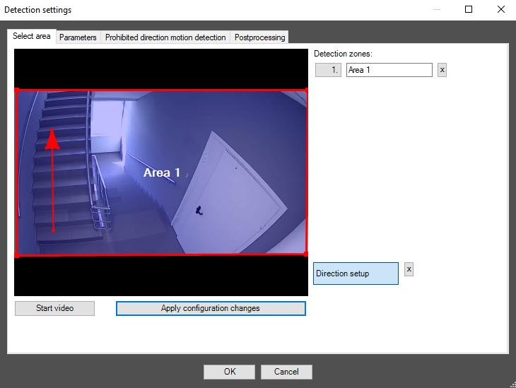
The maximum number of detection zones is 20.
To rename a detection zone, enter a new name in the field to the right of its number. The new name appears in the zone caption on the video image.
Note
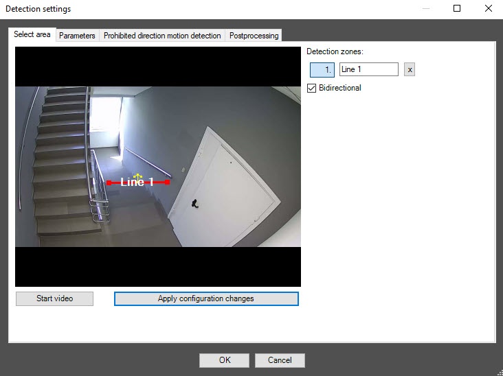
The maximum number of detection lines is 20.
To rename a detection line, enter a new name in the field to the right of its number. The new name appears in the line caption on the video image.
Configuration of the VI detection of prohibited direction software module is complete.