Go to documentation repository
Page History
| Section | |||||||||||||||||||||
|---|---|---|---|---|---|---|---|---|---|---|---|---|---|---|---|---|---|---|---|---|---|
|
Configuring the parameters
To create To configure the Move from area to area detection tool detector, do the following:
- Create the required detector and specify its parameters (see Configuring detectors and their sub-detectors).
- Below the created detector, click Create… → Move from area to area.
By default, the detector is enabled and set to generate events when an object leaves one area and enters another area.
If necessary, you can change the detector parameters. The list of parameters is given in the table:
| Parameter | Value | Description | |||||
|---|---|---|---|---|---|---|---|
| Other | |||||||
| Enable | Yes | The detector is enabled by default. To disable the detector, select the No value | |||||
| No | |||||||
| Name | Move from area to area | Enter the detector name or leave the default name | |||||
| Type | Move from area to area | Name of the detector type (non-editable field) | |||||
| Advanced settings | |||||||
| X-axis offset | 15 | Specify the X-axis and Y-axis offsets as a percentage of the track area to receive events from the specified area. The values must be in the range [1, 40] | |||||
| Y-axis offset | 10 | ||||||
| Basic settings | |||||||
| Event hold time (sec) | 2 |
This is the time period during which the detector waits for the next objects after the first object in the group is detected. If the specified number of objects (specified in the Number of alarm objects parameter) are detected within this time period, the detector generates an event. If no additional objects are detected within the specified time period, the detector doesn't generate an event. | |||||
| Maximum object height | 100 | Specify the maximum object height as a percentage of the frame size for the detector to generate an event. The value must be in the range [0.05, 100]
| |||||
| Maximum object width | 100 | Specify the maximum object width as a percentage of the frame size for the detector to generate an event. The value must be in the range [0.05, 100]
| |||||
| Maximum speed | 500 | Specify the maximum object speed per second for the detector to generate an event. The value must be in the range [0, 500]
| |||||
| Minimum object height | 0.1 | Specify the minimum object height as a percentage of the frame size for the detector to generate an event. The value must be in the range [0.05, 100]
| |||||
| Minimum object width | 0.1 | Specify the minimum object width as a percentage of the frame size for the detector to generate an event. The value must be in the range [0.05, 100]
| |||||
| Minimum speed | 0 | Specify the minimum object speed per second for the detector to generate an event. The value must be in the range [0, 500]
| |||||
| Number of alarm objects | 2 |
This number determines the minimum number of objects that are considered a group and can generate an event. | |||||
| Object class | All classes | Select the object class that must generate an event. The default value is All classes
| |||||
| Vehicle | |||||||
| Person | |||||||
| Trigger on group of objects | Yes | The parameter is disabled by default. If you want the detector to generate an event only for a group of objects, select the Yes value
| |||||
| No | |||||||
To save the parameters of the detector, click the Apply button. To cancel the changes, click the Cancel button.
Configuring detection areas
To configure detection areas, do the following:
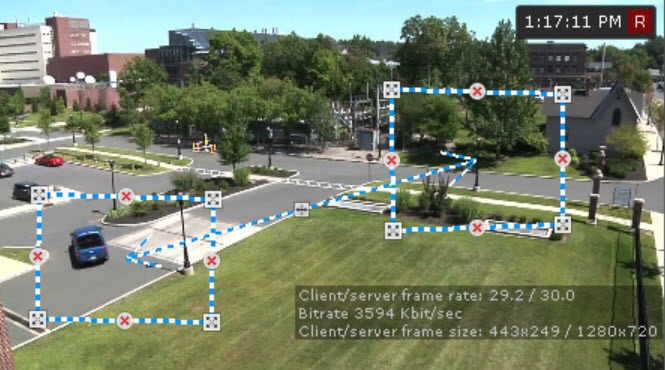
- In the preview window, specify two areas. The detector generates an event
- Set the general parameters (see Setting general parameters of Tracker-based Scene Analytics detection tools). Set two areas in the preview window. The tool is triggered
- if any object moves from one area to the other in the specified direction.
By default, the areas - the areas are located on the right side and the left side of the video image. The
- The anchor points of each area are connected by a two-color dotted line. To reshape the area, drag
- You can resize the area by dragging its anchor points
- . To move the entire area, left-click and drag its border. To add the
- anchor points, click . .
- In the preview window, set
- specify the directions of the object movement. The direction of movement between the areas is indicated by a dotted arrow. To change the direction of movement, click on
- on the direction arrow. The available directions are:
- Left.
- Right.
- Both directions.
- Click the Apply button.
- Click the Apply button. To cancel the changes, click the Cancel button.
| Info | ||
|---|---|---|
| ||
|
Configuration of the Move from area to area detector is completeThe Move from area to area detection tool is configured.


