
Go to documentation repository


Page History
| Info | ||
|---|---|---|
| ||
By Modbus Coil Register, the Digital TheModbus Coil Register refers to the Digital Output, or Coil is meant. It is possible to either read or write the Digital Output. The register size is 1 bit. |
The Modbus Coil Register is configured as follows:
- Go to the settings panel of the Modbus Coil Register object settings panel which that is created on the basis of the Modbus Device object.
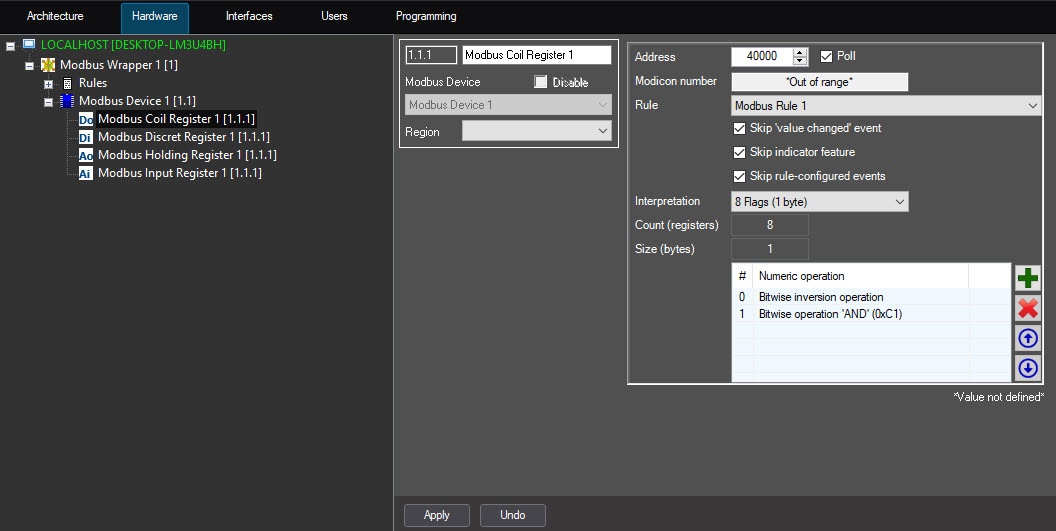
In the Address field (1), enter the Coil Register address in the register map of this device.
Info title Note - The
- registers map is provided by the
- manufacturer.
- From the Value drop-down list (2), select the coil register value: Reset or Set.
- Click the Read value button (3) if it is necessary to read the device register.
- Click the Write value button (4) if it is necessary to specify the selected value to the device register.
- Set the Auto update checkbox (5) if it is necessary to automatically read the register values with the interval specified on the Modbus Device object settings panel.
- The register address is always less than the register number by 1. The register address is specified in the settings.
- Set the Poll checkbox to start polling the Modbus Coil Register. This makes the settings available for editing.
- From the Rule drop-down list, select the Modbus rule to which this Coil Register complies (see From the Rule drop-down list (6), select the rule to which this Register will obey (see Configuring the Modbus Rule).
- Set the Value change checkbox (7) if it is not necessary to display the events on the register value change in the Event Log. Uncheck the Indicator change checkbox (8) if it is necessary to allow displaying of the register values in the plain text on the map Skip 'value changed' event checkbox, so that the Event Viewer window doesn't display the events of Coil Register value change.
- Set the Skip indicator feature checkbox to disable the display of the Coil Register value on the map in text form.
Note title Attention! Value change Сhange of this parameter will be is applied after restarting the you restart the ACFA PSIM Server.
- Set the Config event checkbox (9) if it is not necessary to display the events in the Event Protocol when the rule is triggered. Skip rule-configured events checkbox, so that the Event Viewer window doesn't display the events of rule triggering.
- From the Interpretation drop-down list, select the Coil Register data format:
- Single Flag,
- 8 Flags (1 byte),
- 16 Flags (2 bytes).
- To add a numeric operation to the table, click the
 button.
Info title Note To delete a numeric operation from the table, click the
 button.
You can change the sequences of operations using the following buttons: to move up one position, click the
 button, to move down one position, click the
  button.
 - From the list of operations, select:
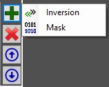
- Inversion.
- Mask.
In the Mask operation settings window: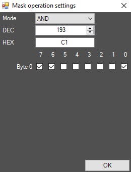
- From the Mode drop-down list, select the logical operator AND (default), OR, or XOR.
- Specify the bitmask value in decimal (DEC) or hexadecimal (HEX) format, or set the corresponding checkboxes.
- Click the OK button to save the settings.
- Click the Apply button to save the settingsClick Apply (10) to save the changes.
The Modbus Coil Register is now configured.
Overview
Content Tools