Go to documentation repository
Page History
...
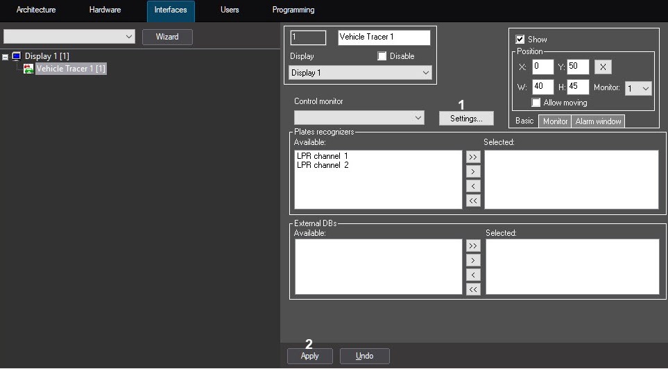
- Go to the Vehicle Tracer settings panel.
- Click the Settings button.
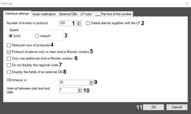
The Settings dialog window will open. In the Number of events in protocol field (1), enter the maximum number of events from 10 to 10000 that may can be displayed in every protocol of the Active monitorMonitor component. The update of the protocol which contains the maximum number of events, is performed in a loop: when the maximum number of events is exceeded, the last event in the queue is deleted.
Info title Note That This entails two protocols:
- the protocol of identified vehicles, containing data about the identified vehicles;
- the alarms protocol, containing data about the vehicles, for which alarms have been registered. The number of alarms is calculated as follows: "Number of events in protocol" minus 2. For example, if 100 is specified as a value of the Number of events in protocol field, then 98 alarms will be displayed in the alarm protocol.
Set the Delete alarms together with the LP checkbox (2) if it is necessary to delete all the events connected to the last number in the queue when exceeding the specified number of events in the protocol.
- Set the Speed switch (3) to the position, corresponding to the Vehiclevehicle's speed unit of measurement . That is to that should be displayed in the Vehicle Tracer window (km/h or miles/h).
- By default, in the Active monitorMonitor events protocol the following data for every vehicle is displayed:
- Video frame;
- Identified LP number;
- Name of LP recognizer;
- Date and time of receiving the data;
- Reason of alarm (only for alarms).
- In case only the identified LP number, name of LP recognizer, and date and time of receiving the data should be displayed for each event in the Active monitor events Monitor events protocol, check the set the Reduced view of protocols checkbox (4).
- You can create additional Active monitorMonitor components. If the alarms protocol should be displayed only in the main interface component of Active monitor and Monitor and not in the additional ones, check set the Protocol of alarms only in main Active Monitor window checkbox (5).
- By default, the number of additional Active monitor components to be displayed is Monitor components that should be displayed is not restricted. If only the most recent additional additional Active monitor component Monitor component should be displayed, check the set the Only one additional Active Monitor window checkbox (6).
- Set the Do not display the regional code checkbox (7) if it is necessary to hide the Regional code field from the Active Monitor component.
Set the Display the fields of an external DB checkbox (8) if it is necessary to display the fields of an external DB in the Active Monitor component when the license plate is found in the external license plate database (see Assigning names to table columns containing LP numbers).
- In the DB timeout, s field (9), specify in seconds the timeout for connecting to the selected Auto PSIM servers when the Event search in the Recognizers DBs window is opened (see Configuring the events search). If the specified time is exceeded, all connection attempts are terminated and a list of Servers to which it was not possible to connect is displayed.
- In the Interval between start and end date field (10), specify the period in days between the start and end day of searching the license plate and of the alarm's initializing when the license plate is found in the recognizer database.the expiration time of the suspect vehicle profile. The default value is 7 days. After that, the specified interval will be automatically moved to the form for entering a new suspect vehicle profile in the Active tracking database as a difference between the Start date and Expiration date fields (see Creating the Active tracking database).
- Click the Ok button Click OK (11) to save the changes and return to the control settings panel of the Vehicle Tracer.
- Click the Apply (2) button to save the changes on the Vehicle Tracer settings panel.
The interface settings of Setting up the Vehicle Tracer interface window are completedis complete.


