Configuration of the VI detection of prohibited direction module includes general settings and configuration settings: detection zone, configuration parameters, and detector characteristics.
General settings
- Go to the settings panel of the VI detection of prohibited direction object that is created on the basis of the Camera object on the Hardware tab of the System settings window.

- In the Frames processed per second [1, 100] field, specify the number of frames in the range from 1 to 100 that the detector processes per second. The default value is 12 (recommended). You can specify only a positive integer. If you enter a number outside the range from 1 to 100, it is automatically changed to the nearest border value. If you leave the field blank, it automatically returns to the default value when you save the settings.
- In the Scale frame to (px) field, specify in the range from 420 to 1920 the width of the frame in pixels after scaling. The height of the frame is calculated automatically as the value specified in the setting, divided by 1.77777(7). The default value is 640, that is, the frame size after scaling is 640x360. The setting doesn't affect the resolution of the video stream and is used to reduce the load on the CPU, it is displayed in the logs and in the debug window.
- Set the Use GPU checkbox if it is necessary to use a graphics processor (NVIDIA GPU) when working with a neural network.
- Set the Show objects on image checkbox if it is necessary to outline the detection zones with a red border on the Video surveillance monitor when a motion event is generated in the prohibited direction. The detection zones are specified in the detector settings on the Select area tab.
- From the Detection filtering drop-down list, select the filter that you want to use: Object filter, Object counting filter, Do not use filter (default). You can configure filters on the Postprocessing tab of the Detection settings window.
- Click the Configuration setup button. As a result, the Detection settings window opens.
The Prohibited direction motion detection tab
- Go to the Prohibited direction motion detection tab.

- In the Sensitivity [0, 1] field, specify in the range from 0 to 1 the sensitivity of the detector to detecting moving objects in the detection zone. The higher the sensitivity, the less noticeable an object can be detected. The default value is 0.50. If you select the Area mode in the Mode parameter, this setting is disabled.
In the Intensity [1, 50] field, specify in arbitrary units in the range from 1 to 50 how noticeable the object's movement in the detection zone must be for the detector to generate an event. The default value is 10. If you enter a value out of range, it is automatically changed to the appropriate border value. If you select the Line mode in the Mode parameter, this setting is disabled.
In the Duration [1, 100] field, specify in arbitrary units in the range from 1 to 100 the duration of the object’s movement in the prohibited direction. It can be used when analyzing dense passenger flows, when an object making its way in the opposite direction appears in the camera’s FOV only for short time intervals, and the rest of the time is hidden from view by the crowd. The default value is 40. If you enter a value out of range, it is automatically changed to the appropriate border value. If you select the Line mode in the Mode parameter, this setting is disabled.
- In the Head size [0, 1] field, specify in the range from 0 to 1 what part of the video image height is the human head. The default value is 0.50. If you select the Line mode in the Mode parameter, this setting is disabled.
- In the Allowable deviation angle [1, 180] field, specify in degrees in the range from 1 to 180 the permissible deviation from the direction of movement specified by the red arrow in the prohibited direction. The default value is 45. If you enter a value out of range, it is automatically changed to the appropriate border value. If you select the Line mode in the Mode parameter, this setting is disabled.
- In the Mode parameter, select Line if the detection zone is determined by lines. The Area mode is selected by default—the detection zone is determined by a polygon. The display of the Select area tab depends on the selected mode.
- In the Number of analytics streams field, specify the number of video streams that are used for neural network analytics. The default value is 4.
The Select area tab
- Go to the Select area tab.
- Click the Stop video button to pause the video.
- Specify parameters of a detection zone:
- When you select the Area mode (default) on the Prohibited direction motion detection tab:
- By default, the detection zone is outlined with a red border. You can change the borders of the detection zone using the mouse by clicking its number in the list on the right, the number of the selected zone is highlighted in blue. Move the borders of the detection zone.
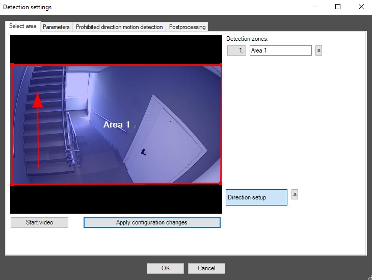
- To create a new detection zone, click the video image in the required point and use the mouse to specify its borders. To delete a detection zone, click the
 button to the right of the zone name.
- To specify a prohibited direction, using a mouse, turn the red arrow in the required direction. To delete a direction arrow, click the button to the right of the Direction setup item that must be selected, that is, highlighted in blue.
- When you select the Line mode (default) on the Prohibited direction motion detection tab:
- By default, a red detection line with a yellow arrow is displayed. The yellow arrow indicates a prohibited direction. You can change the detection line by clicking its number in the list on the right. The number of the selected line is highlighted in blue. You can move both sides of the line.
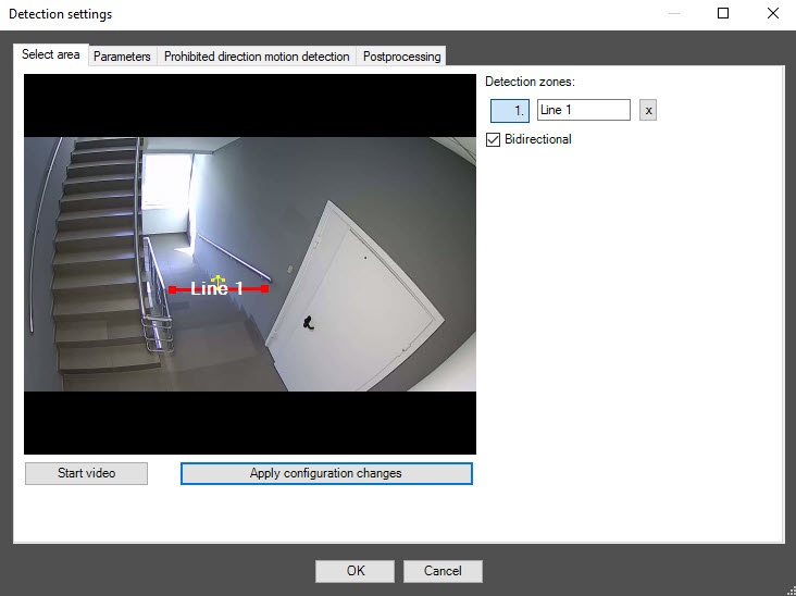
- To create a new line, click the video image in the required point and use the mouse to specify its borders. To delete a detection line, click the button to the right of its name.
- Set the Bidirectional checkbox for the detector to generate an event when a line is crossed in both directions.
- Click the Apply configuration changes button to save all changes.
- To start video playback, click the Start video button.
The Parameters tab
- Go to the Parameters tab of the detector settings window. This tab displays the parameters of the used configuration. If you do not need to change the configuration, skip steps 2 and 3 and go to the next tab.
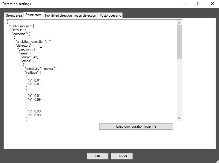
- To use custom configuration, click the Load configuration from file button.
- In the standard Windows search window that opens, specify the path to the configuration file in JSON format.
The Postprocessing tab
You can use this tab to configure object filters or object counting filters according to the option selected from the Detection filtering drop-down list in the basic settings of the detector.
Object filter
- To enable the object filter, select Object filter from the Detection filtering drop-down list in the basic settings of the detector.
- Go to the Postprocessing tab.
- From the Object filter list on the left, select one or more objects. If these objects are detected in the frame, the detector events are filtered. The events aren't displayed in the event viewer and on the screen.

- To apply the filter, click the Apply filter configuration button.
Object counting filter
- To enable the object counting filter, select Object counting filter from the Detection filtering drop-down list in the basic settings of the detector.
- Go to the Postprocessing tab.
- Click the Add count filter button. In the section on the right, select one or more object counting filters.

- In the Min and Max fields, set the lower and upper threshold values for each object counting filter. If the number of objects of a given type in the detection area is within this range, the detector generates an event that is also displayed in the event viewer and on the screen. If the number of objects is greater or less than the set range, or there are no objects at all, then all events are filtered out and aren't displayed in the event viewer or on the screen.
- To apply the filter, click the Apply filter configuration button.
Click the OK button to save all settings of the detector. The Detection settings window closes, and you return to the detector settings panel.
To save all changes, click the Apply button on the settings panel of the VI detection of prohibited direction object.
Configuration of the VI detection of prohibited direction module is complete.
