
Go to documentation repository
Documentation for Axxon One 3.0/3.1 version. Documentation for Axxon One 2.0 version is also available.

On the page:
General information
The map in Axxon One is used to visualize and manage devices at a protected facility. The following can be used as a base for the map:
- An uploaded bitmap or vector image (building plan, site map).
- Data from map providers (OpenStreetMap, Google Maps).
Attention!
- To work with maps from map providers, you must have a separate license (see Map providers).
- The ability to create, edit, and delete maps depends on the settings of the access permissions for the user role in the Map control setting (see Role).
You can work with the map in three modes:
- 3D mode—Map and layout are available.
- 2D mode—Only map is available.
- Immersion mode—Video on top of the map.
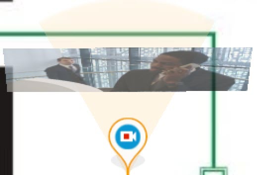
The map contains icons of cameras, inputs, outputs, macros, and ACFA devices. The field of view and the area with live video are displayed for each camera.
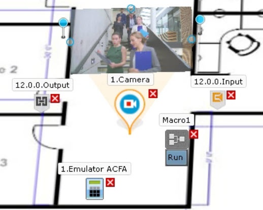
The map can either have one layer or have several floors.
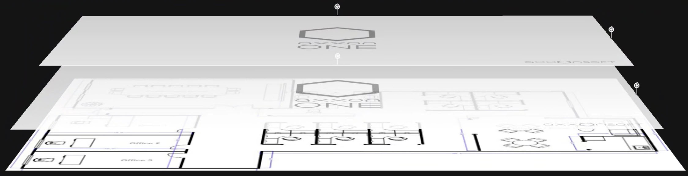
Map edit mode
You can create maps, add objects to them, and configure these objects in the map edit mode. To go to the edit mode:
- Select the required layout on the layout panel (see Configuration of layouts).
- Click the Open layout control menu
 button in the upper left corner of the panel.
 - Select Edit layout/map.
You switched to the edit mode.
Manage maps
Add a map
To add a map:
- Go to the map edit mode.
- Click the Open layout control menu button in the upper left corner of the panel.
- If the map isn't added to the layout, select Add new map.
- Or:
- Select Edit layout/map.
- Click the Map
 button in the lower right corner of the panel.
 - Click the Add new map
 button in the lower left corner of the panel.
- Or:
- Select Edit layout/map.
- Click the Map button in the lower right corner of the panel.
- Right-click the map.
- In the menu that opens, select Add new map.
- In the window that opens, specify the map settings listed in the table.
Setting Value Description New Map Name Enter the name of the map Type Select a data source from the drop-down list. Available types are specified in the domain options (see Map providers) Bitmap or vector image - Bitmap image consists of a grid of pixels, each of which has a specific color.
- Vector image is based on mathematical formulas and consists of lines, curves, and shapes that are defined using coordinates
Google Map There are three types of Google maps available:
- Google Hybrid
- Google Maps
- Google Satellite
OpenStreetMap Provides free access to cartographic data Address The setting is available only when you select the following values in the Type setting:
- Google Map
- OpenStreetMap
Enter the address, postal code, or geographic coordinates of the required area on the map and click the
 button. You can zoom using the zoom slider or the mouse wheel and navigate the map using the standard navigation method
Image Click the
 button and select the required file that will be used as a graphic plan of the protected facility. If you don't select any file, a map with a white background will be created.
Setting requirements:
- The setting is available only when you select Bitmap or vector image in the Type setting.
- Supported formats:
- Bitmap image: PNG, JPG, JPEG, JPE, GIF, BMP.
- Vector image: SVG.
- The file size must not exceed 4 MB.
- The maximum image size is 4 million pixels (the number of pixels in a 2000x2000 resolution). The map isn't created if you select a file larger than the permitted size
Share map Select who has access to the map Any user The map is available to all users Not shared The map is only available to the current user Roles The map is available only to those roles that are selected in the Roles setting Roles 
By default, the checkbox is clear, and roles are unavailable. To set the checkbox for the required role, select Roles in the Share map setting. You can create roles on the Users tab (see Role) 
- Click the Apply
 button. To cancel actions, click the Cancel
  button.
 - Click the Save
 button. To cancel actions, click the Cancel
  button.
A map is added.
Bind a map to a layout
You can bind a map and a layout. When you go to a layout, the map that is bound to it will automatically open. To bind a map to a layout:
- Select a layout that you want to bind to a map on the layout panel or create a new layout (see Configuration of layouts).
- Go to the map edit mode.
- Click the Map button in the lower right corner of the panel.
- Select the created map or create a new map (see Add a map)
- Click the Save button. To cancel actions, click the Cancel button.
The map is bound to the layout  . If you save the layout with the map open in 2D mode, then when you go to this layout, the map will always open in this mode
  .
.
Change map name
To change the map name:
- Go to the map edit mode.
- Left-click the corresponding tab in the lower left corner of the screen and enter a new name for the map.
- Click the mouse anywhere on the screen.
- Click the Save button. To cancel actions, click the Cancel button.
The map name is changed.
Change the type or image of the map
To change the type or image of the map:
- Go to the map edit mode.
- Right-click any place on the map and select Map properties.
- In the window that opens, specify the map properties. This window is similar to the map creation window (see Add a map).
- Click the Apply button. To cancel actions, click the Cancel button.
- Click the Save button. To cancel actions, click the Cancel button.
The type or image of the map is changed.
Change the order of map tabs
By default, tabs with maps are arranged in the order they were created in the system. To change the order:
- Go to the map edit mode.
- Select a tab and drag it to the required position.

- Click the Save button. To cancel actions, click the Cancel button.
The order of the map tabs is changed.
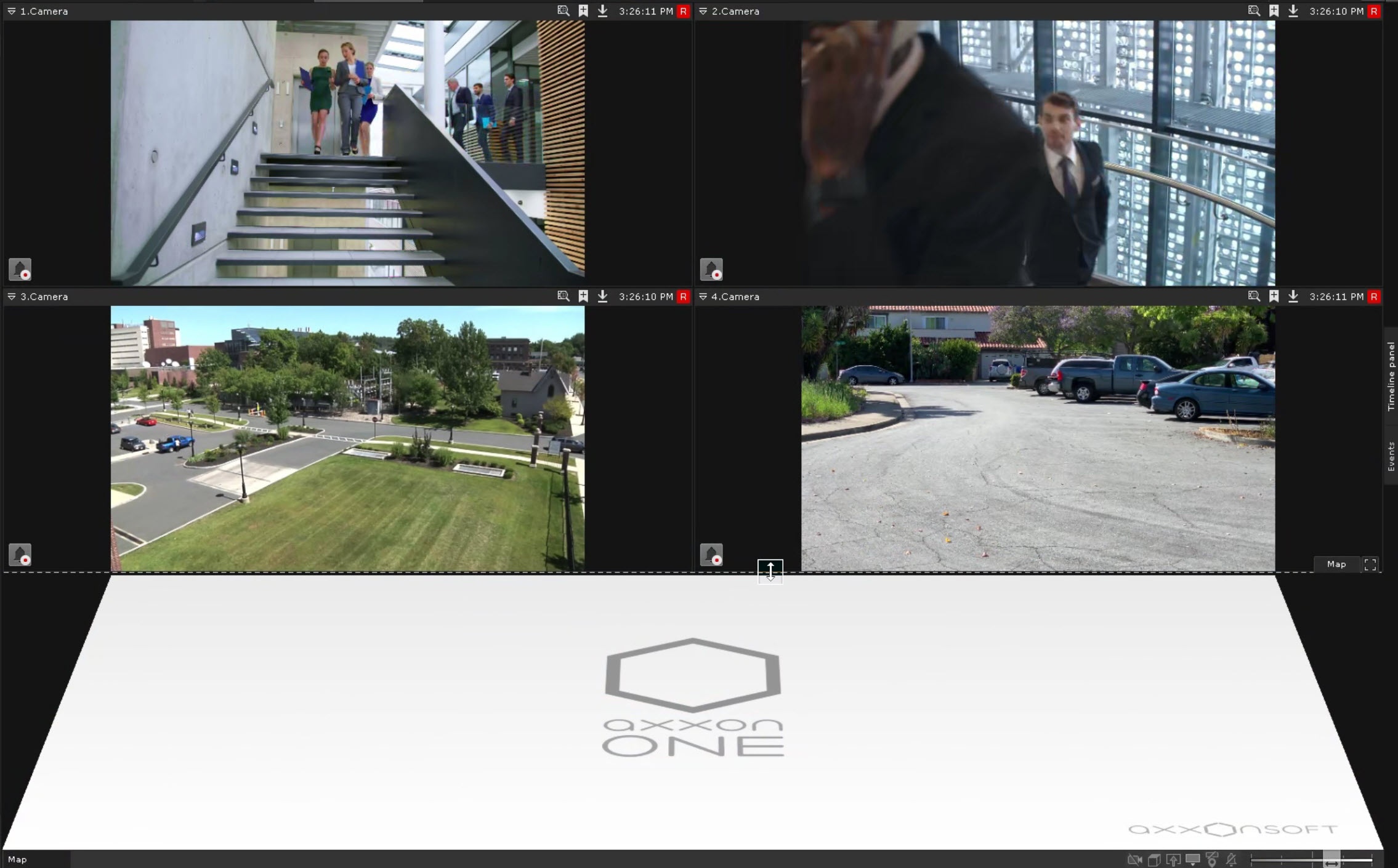
Change the tilt of the map surface
You can change the tilt of the map surface by changing the border of the map and layout.
There are two ways you can go to 2D map viewing mode:
- Click the
 button to the right of the Map button. The layout closes, and the map is displayed full-screen. To return to 3D map viewing mode, click the Map button. To hide the map completely, click the
  button.
 - Click the Top view
 button on the control bar in the lower right corner of the screen. This keeps the layout open, and the map is displayed in the same location. To return to 3D map viewing mode, click the Top view
  button.
Note
If the map is hidden, the control bar in the lower right corner of the screen isn't available.
Change the map zoom and shift the map
You can change the map zoom and shift the map either manually or automatically.
Note
Automatic change of the map zoom and shift of the map are performed if you set the checkbox in the Enable map auto zoom on alarm setting (see User Interface).
- When an alarm occurs, the map automatically changes zoom and position to display all alarmed cameras.
- After all alarms end, the map returns to its original zoom and position.
- Automatic change of the zoom and position stops when you interact with the map or camera.
- You can also change the zoom of the map manually using the mouse wheel or the zoom bar.
After the map is zoomed in, you can move the map with the mouse (by pressing and holding the left mouse button) in any direction.
Switch between maps
In any mode, you can switch between maps created in the system. There are two ways to switch between them:
- On the map panel in the lower left corner of the screen.
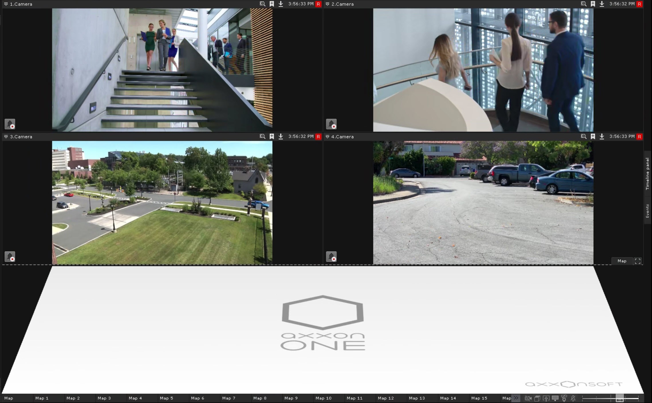
If you created many maps, not all tabs can fit on the panel. Click the List of all maps button and select the required map in the window that opens.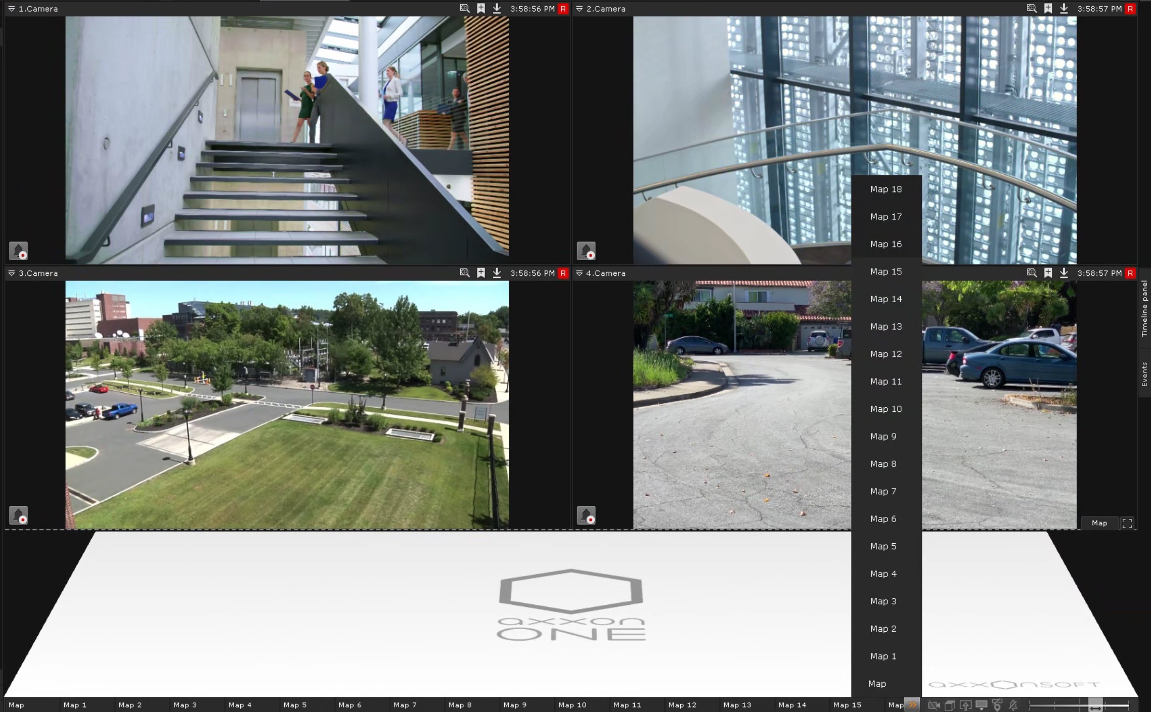
- Left-click a transition icon on the map if a transition was created. The caption of the icon indicates the name of the map to which the transition occurs:
 .
.
Show and hide the map
You can view the map from all surveillance modes except archive mode. To view a map, click the Map  button in the lower right corner of the screen.
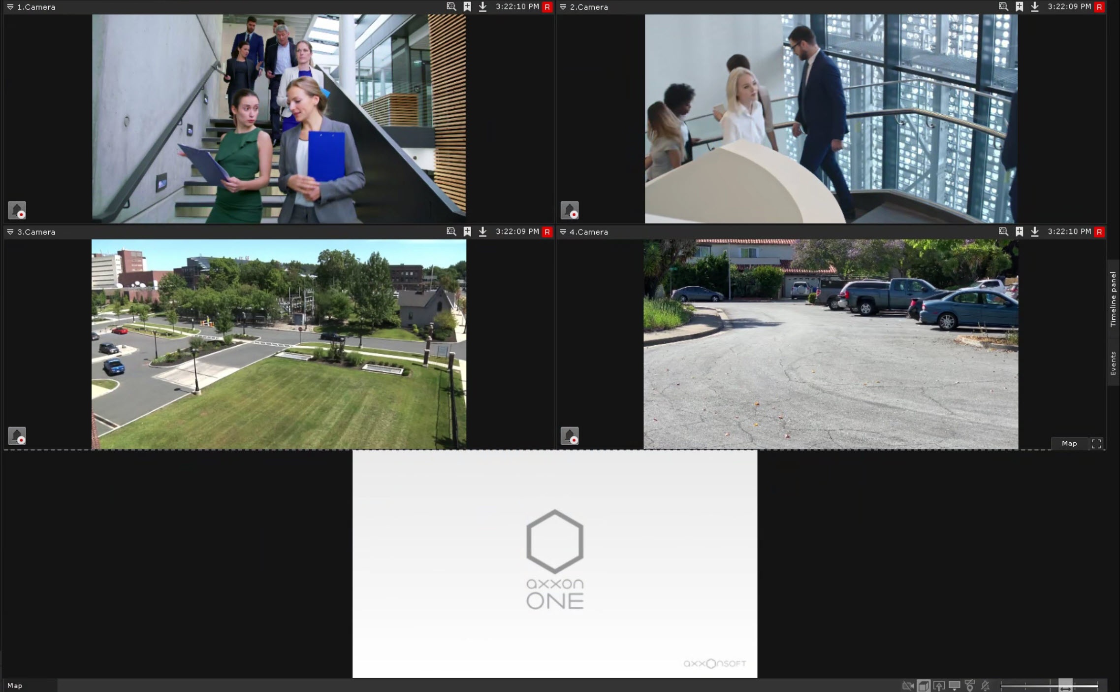
The map is displayed in a 3D mode, with the layout moving to the top of the screen and decreasing in size.
To exit map viewing mode, click the Map button again. The map also automatically hides when you zoom in on any surveillance window to its maximum size (see Scaling the Surveillance window). When you zoom out on a surveillance window to its minimum size, the map is displayed again.
Delete a map
To delete a map:
- Go to the map edit mode.
- Right-click anywhere on the map and select Delete map. Or click the Delete map
 button next to the map name.
 - Click the Save button. To cancel actions, click the Cancel button.
The map is deleted.
Add objects to the map
You can add the following types of objects to the map:
- Cameras
- Inputs (that are on)
- Outputs (that are on)
- Macros
- Transitions to other maps
- ACFA devices.
After you add objects to the map from the objects panel, when you left-click an object, a line is drawn that shows the object's location on the map. You can also use the context menu of the icons on the map to control cameras, inputs, outputs, macros, and ACFA devices.
Add cameras to the map
You can add a camera to the map in one of the following ways:
- You can add a camera from a surveillance window:
- Go to the map edit mode.
- Click the Click to show context menu
 button in the surveillance window.
 - Select Add new map in the menu.
- You can add a camera from the objects panel by dragging:
- Go to the map edit mode. To delete a camera from the map, click the button.
- Click the Objects panel
 button (see Object panel).
 - Drag the camera to the map. To delete a camera from the map, click the button.
- Go to the map edit mode. To delete a camera from the map, click the
- You can add a camera via the context menu of the objects panel:
- Go to the map edit mode.
- Click the Objects panel button (see Object panel).
- Right-click the required camera and select Add to map. To add all cameras in a group/server/domain, right-click the name and select Add to map. To delete a camera or cameras in a group/server/domain from the map, click the button.
A camera or cameras in a group/server/domain are added to the map. If a camera has Latitude, Longitude, and Azimuth specified (see Camera), the camera icon is automatically positioned on the map according to the specified coordinates. If coordinates are not specified, the camera icon is automatically added to the center of the visible map area.
Attention!
- If the values of the Longitude and Latitude settings are 0, the Azimuth value isn't taken into account when you add the camera to the map.
- Azimuth is measured in degrees from north clockwise, where:
- 0 degrees indicates the field of view is facing north (up).
- 90 degrees indicates east (right).
- If the camera has an embedded GPS tracker, the camera location on the map changes automatically based on the received data.
- If you change the settings of the camera's coordinates, you must delete the camera from the map and re-add it for the new coordinates to take effect.
Cameras are added to the map. Possible states of cameras and their icons:
| Icon | State |
|---|---|
| The camera is disarmed. Recording to the archive isn't performed |
| The camera is disarmed. Recording to the archive is performed |
| The camera is armed. Recording to the archive isn't performed |
| The camera is armed. Recording to the archive is performed |
| The camera is alarmed. Recording to the archive is performed |
| Connection with the camera is lost |


Interface control and configuration commands:
| Menu command | Result |
|---|---|
| Arm |
|
| Arm in private mode (see Arm and disarm a camera) |
|
| Disarm |
|
| Show video | The video area is displayed
|
| Hide video | The video area isn't displayed |
| Show layout | The selected camera is displayed on a dynamic layout. To display several selected cameras on a dynamic layout, see Select several cameras to display on a dynamic layout |
| Copy | If you left- or right-click any cell in the layout, the video from the copied camera will be displayed in that cell. The copied camera remains visible in the layout until you switch to another layout or restart the client |

Add an output to the map
To add an output (see Output) to the map:
- Go to the map edit mode.
- Click the Objects panel button (see Object panel).
- Drag the required output to the map. To delete an output from the map, click the button.
An output is added to the map. Possible states of outputs and their icons:
| Icon | State |
|---|---|
| Output is activated (closed) |
| Output is in a normal state (open) |


Note
When the state of an output is changed with a macro, the output icon on the map doesn't change (see Programming).
Interface control and configuration commands:
| Menu command | State |
|---|---|
| Output off |
|
| Output on |
|
Note
You cannot switch the state of an output from the map if macros with the corresponding action are present in the system (see Switch on/off output).
Add an input to the map
To add an input (see Input) to the map:
- Go to the map edit mode.
- Click the Objects panel button (see Object panel).
- Drag the required input to the map. To delete an input from the map, click the button.
An input is added to the map. Possible states of rinputs and their icons:
| Icon | State |
|---|---|
| The camera is armed. The input is in a normal state |
| The camera is armed. The input is alarmed |
| The camera is disarmed. The input is in a normal state |
| The camera is disarmed. The input is alarmed |


For the Tibbo board inputs (see Setting up Tibbo relay/loop boards), the map also displays temperature and humidity values.

The appearance of the input icon depends on the camera to which it belongs.
Add a macro to the map
To add a macro (see Programming) to the map:
- Go to the map edit mode.
- Click the Objects panel button (see Object panel).
- Click the Programming button in the lower left corner of the screen.
- Drag the required macro to the map. To delete a macro from the map, click the button.
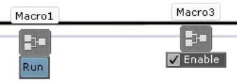
By default, the start button is displayed on the map for the Event rules macro. The enable/disable checkbox is displayed on the map for the Cycle rules macro (see Configuration of macros). To hide macros, clear the Show buttons checkbox. In this case, macros are only available via the context menu.
A macro is added to the map.
Commands to control macros and configure the interface:
| Menu command | Condition | Function performed |
|---|---|---|
| Run | Event rules macro | Start a macro |
| Enable | Disabled cycle rules macro | Enable a macro |
| Disable | Enabled cycle rules macro | Disable a macro |
You can also control macros using the Run button and the Enable checkbox. By default, macro icons don't change.
Add ACFA devices to the map
To add ACFA devices (see Documentation ACFA software package 16.0) to the map:
- Go to the map edit mode.
- Click the Objects panel button (see Object panel).
- Click the ACFA devices button in the lower left corner of the screen.
- Drag the ACFA device to the map. You can add one ACFA device to the map only once. To delete an ACFA device from the map, click the button.
You can add an ACFA device to the map as:
| Display type | Visual example | Description |
|---|---|---|
| Default (ACFA device icon) |
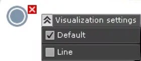
| By default, the icon is displayed on the map for all ACFA devices. The icon is displayed together with other display types (Area, Line). To hide the icon on the map, clear the Default checkbox. Some ACFA devices can display multiple icon options (for example, Managing the access point of the Server "Sigur" integration module) |
| Area |
| For some ACFA devices, area display is available. You can configure the area as a polygon. To display the area on the map, set the Area checkbox |
| Line |
| For some ACFA devices, line display is available. You can configure the line as a polyline. To display the line on the map, set the Line checkbox |
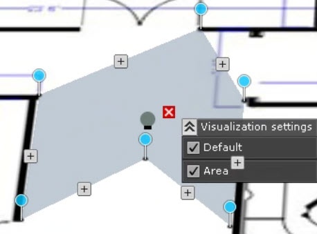
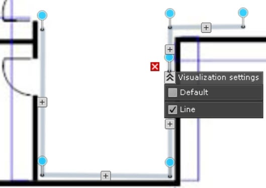
ACFA devices are added to the map.
Add transitions to another map
You can add a transition to another map in one of the following ways:
- By dragging:
- Go to the map edit mode.
- Using your mouse, select the tab of the map to which you want to create a transition and drag the transition icon
 to the required place on the map. To delete a transition from the map, click the button.
- Using the context menu of the map:
- Go to the map edit mode.
- Right-click anywhere on the map.
- Select Add transition to map.
- Select a map created in the system to which you want to create a transition. To delete a transition from the map, click the button.
A transition to another map is added.
Group objects into a cluster
When cameras have the same coordinates or are located close to each other, they are automatically grouped into a cluster.
- Each cluster is displayed on the map as a circle, with the total number of cameras in the cluster indicated in the center.
- Inputs, outputs, macros, and ACFA devices can be grouped into clusters.
When you right-click a cluster, a list of all objects included in that cluster is displayed.
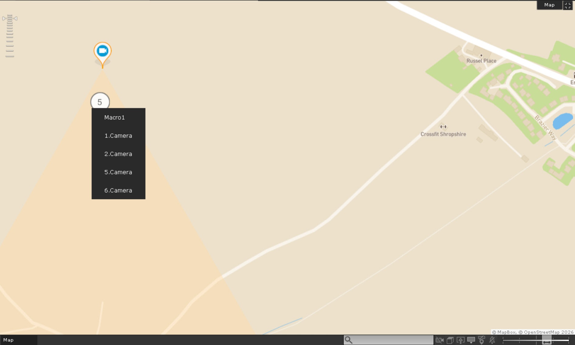
When you select a specific object from the list, it is displayed next to the cluster.
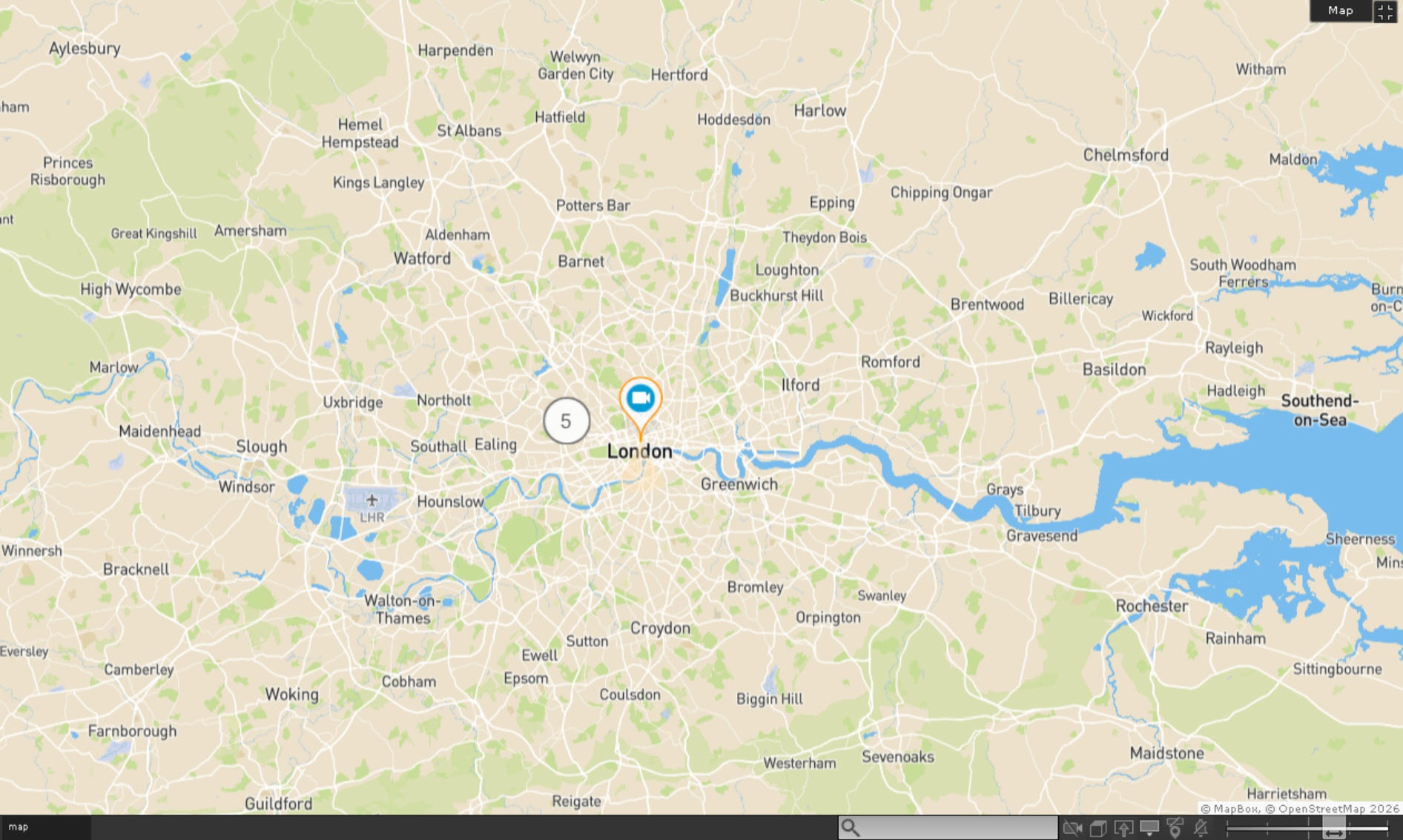
When you left-click an icon of an object on the map, a context menu opens. You can use this menu to manage the object. To hide the list of objects and display them on the map, simply zoom out on the map (see Change the map zoom and shift the map).
If there are multiple clusters close to each other on the map, zooming out merges them into a new cluster. The total number of objects in all child clusters is displayed in the center of the new cluster.
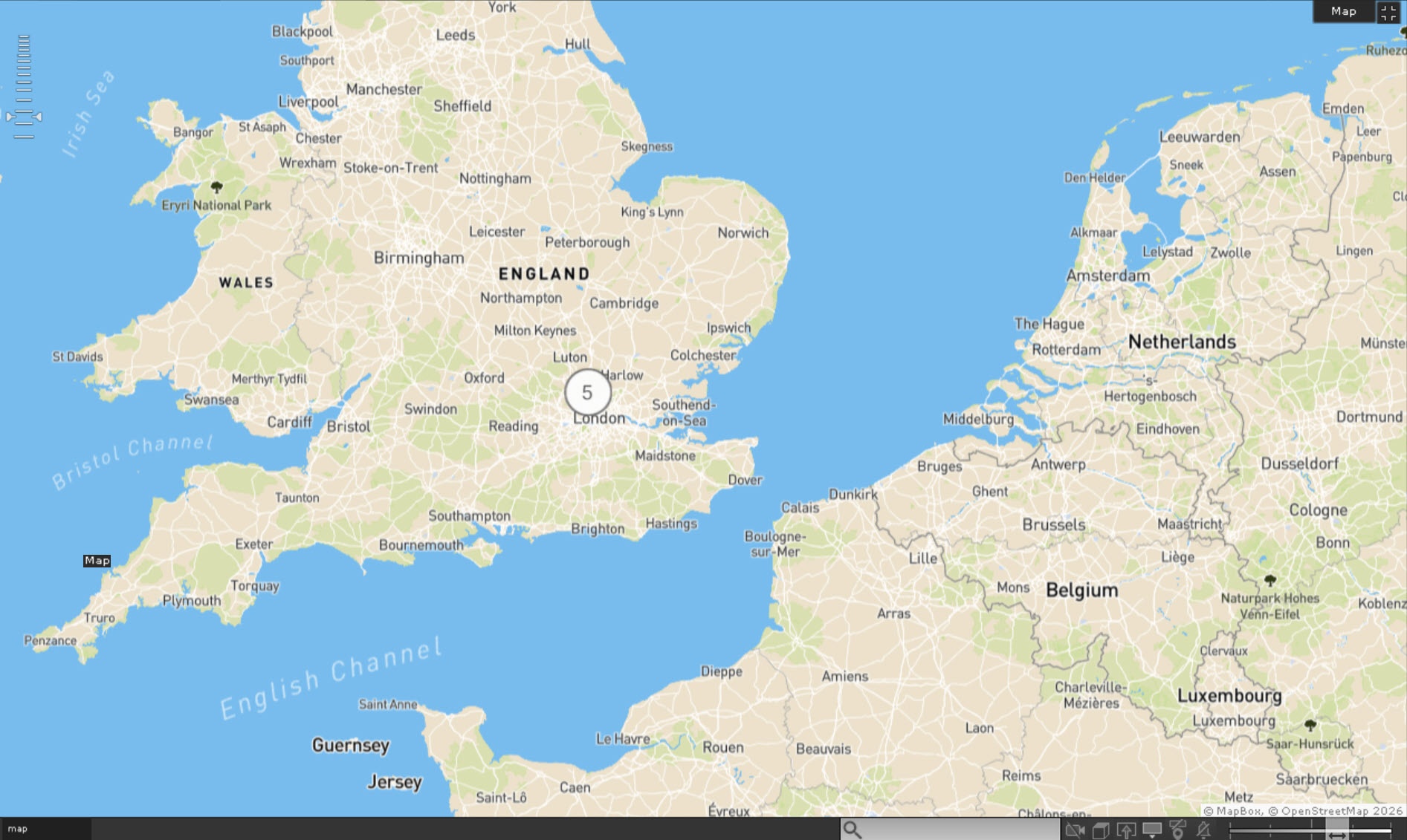
When you click a merged cluster, the map is automatically zoomed in, and child clusters are displayed.
Select several cameras to display in a dynamic layout
To display cameras selected on the map in a dynamic layout:
- Press the Ctrl key and select cameras by left-clicking the icon.
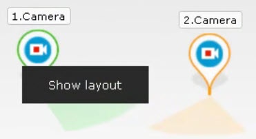
- Click the Show layout button.
The selected cameras are displayed on a dynamic layout that is removed when you switch to another layout (see Configuration of layouts).
Delete objects from the map
To delete objects from the map:
- Select the layout from which you want to delete the object (see Configuration of layouts).
- Go to the map edit mode.
- Click the Delete from map button next to the object. Or right-click the icon of an object and select Remove from map.
Objects are deleted from the map.
Personalization of the map
You can change some settings of the map in view mode using the controls in the lower right corner of the screen.
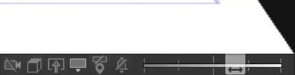
| Button | Function |
|---|---|
| Enable/disable the display of unavailable devices |
| Enable/disable the top view |
| Go to the layout with a camera |
| Go to immersion mode |
| Enable/disable 3D display of icons |
| Enable/disable the display of device names and IDs on the map |
| Enable/disable the vibration of the camera icon when an alarm occurs |
| Change the transparency of the video image. At the far left position of the slider, the video image isn't visible on the map; at the far right position, the video image isn't transparent |



Change the icon size
To change the icon size:
- Go to the map edit mode.
- Use the slider
 to change the icon size. At the far left position, the icons are the smallest size; at the far right, the icons are the largest.
 - Click the Save button. To cancel actions, click the Cancel button.
The icon size is changed.
Configuration of cameras on the map
Configuration of a camera in a standard map view mode
After you add cameras (see Add cameras to the map) to the map:
- Move the camera icon
 on the map to a place corresponding to the actual location of the device in the protected territory.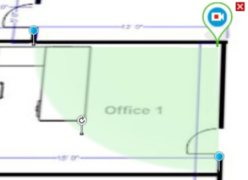
- Move the camera's field of view to the required direction using the
 button.
 - Use the anchor points
 to change the camera's field of view on the map according to the actual situation in the protected territory.
 - Right-click the camera's field of view to display it.
- In the menu that opens, select Show video.
Note
You can configure the Show video/Hide video item outside of the layout/map edit mode, and the setting remains until you restart the client.
- Configure video image area:
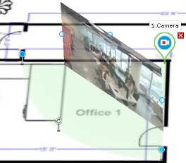
Attention!
- To display a video image area when you use a fisheye camera, select Ceiling in the Camera position setting (see Configuring fisheye cameras) and set the camera's field of view as a circle. Then the video image will be displayed directly within the specified area.
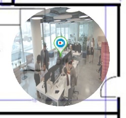
- For cameras with an Immervision lens, select PTZ in the View type setting (see Configuring fisheye cameras). If a fisheye camera has a different field of view, the video image display is unavailable when the camera is positioned on the ceiling.
- Use the dots
 on the video image to adjust the size of the video image area. To do this, left-click the dot and drag it to the required position.
 - Use a dot to change the tilt angle of the area.
Note
When you work with the map, you can switch the video display mode to "flat" (see Personalization of the map).
- To display a video image area when you use a fisheye camera, select Ceiling in the Camera position setting (see Configuring fisheye cameras) and set the camera's field of view as a circle. Then the video image will be displayed directly within the specified area.
Configuration of a camera in a standard map view mode is complete.
Overview
Content Tools